By Gan Liu
Abstract
With the rapid evolution of autonomous driving and Vehicle-to-Everything (V2X) technology, traditional physically isolated traffic signs and markings (I0 to I5 levels) can no longer meet the high-dimensional information interaction demands of “Human-Vehicle-Road-Cloud” collaborative systems. As the core carrier of networked transportation infrastructure, digital traffic signs and markings convert geographic information, traffic regulations, and environmental status into machine-readable structured digital data, evolving toward a next-generation intelligent roadside system characterized by “spatial integration, information sharing, and same-modality collaborative application.” Building on traditional digital roadside technology, this paper introduces the advanced architecture of “intelligent connected three-level traffic signal guidance control,” and examines in depth the same-modality spatial association and control coupling mechanisms of digital markings and signs in corridor path guidance, dynamic lane function management, and adaptive signal control. The paper systematically analyzes key bottlenecks including system architecture, technical indicators, and dynamic-static information conflicts, and looks ahead to the future landscape of full-stack autonomous driving supported at the infrastructure level.

1. Research Background: Paradigm Shift from Physical Media to Digital Networked Infrastructure
1.1 Driving Forces in the V2X and Smart Transportation Era
V2X (Vehicle-to-Everything) technology organically connects people, vehicles, roads, and cloud platforms, achieving qualitative leaps in information acquisition, perception fusion, and collaborative control. Its core macro-objective is to substantially improve traffic efficiency, reduce traffic accident rates, and cut carbon emissions.
In terms of technological trajectory, global V2X development is progressing through three stages:
- Connected Vehicle Stage (1996–2015): Leveraging 2G/3G/4G networks with basic connectivity, primarily serving infotainment and navigation applications.
- Intelligent Connected Stage (2016–present): C-V2X and 5G NR-V2X technologies advancing on parallel tracks, with Advanced Driver Assistance Systems (ADAS) and preliminary vehicle-road collaborative interaction beginning to be deployed.
- Smart Transportation Stage (future): Entering a comprehensive era of vehicle-road collaborative interaction, with all-weather, all-scenario smart mobility and connected services as the core driver. The defining characteristic of this stage is the proactive digital transformation of roadside infrastructure, enabling roads to interact with vehicles at millisecond-level latency.
1.2 Road Intelligence Grading and Its Collaborative Requirements for Signs and Markings
Parallel to the SAE’s L0–L5 autonomous driving classification, road infrastructure intelligence is graded from I0 to I5:
- I0/I1: Traditional purely physical signage and basic electrified signs and markings.
- I2/I3: Introduction of digital networked signs and markings, with preliminary digital information publishing and transmission capability.
- I3/I4/I5: Advancing toward higher-order intelligence, requiring signs and markings systems to possess high-precision intelligent perception, edge computing, and ubiquitous networked communication capabilities, achieving comprehensive “spatial-temporal” digital collaboration.
As autonomous driving advances toward L4/L5, the conventional “visual recognition” mode of traffic signals reveals fundamental limitations: hazard information beyond the line of sight cannot be transmitted in advance; persistent temporal gaps exist between static maps and real-time road conditions; and it cannot support machine-readable structured information encoding, making high-redundancy interaction with autonomous driving perception and decision-making systems impossible. Accordingly, signs and markings must break free from their historically independent physical constraints and move toward digital association and same-modality shared application.
2. Conceptual Connotations and Spatial Association Mechanisms of Digital Traffic Signs and Markings
2.1 Concept Definition and System Architecture
A digital traffic signs and markings system refers to an intelligent transportation infrastructure system that uses digital communication to convey geographic information, traffic regulation information, and environmental status information to intelligent and automated vehicles and cloud platforms. It constitutes intelligent infrastructure compliant with high-order V2X scenario requirements, formed by the deep integration of four core subsystems: perception modules, roadside computing units (SDCU), multi-modal communication components, and the physical bodies of signs and markings.
2.2 Digital Association Sharing and Same-Modality Application of Signs and Markings
In traditional traffic engineering, signs (such as directional, speed limit, or divergence notices mounted on gantries) and markings (such as lane dividers painted on road surfaces) are spatially separated and convey information in a one-way, mutually independent, and fixed manner. Within the digital vehicle-road collaborative framework, signs and markings achieve “same-modality” application, with their association mechanisms expressed across three core dimensions:
2.2.1 Spatial Continuity Sharing (Vertical and Horizontal Visual/Digital Complementarity): Digital traffic signs handle long-range, macro-level traffic regulation and event announcements (vertical-plane visual recognition), while digital traffic markings (smart road markers) handle short-range, micro-level lane-level trajectory guidance (horizontal-plane visual recognition). The two achieve millisecond-level synchronization of spatial coordinates and publishing timing through roadside edge computing units.
2.2.2 Unified Information Encoding Modality: Whether the content displayed by signs (such as variable lanes or segment passage status) or the presentation form of markings (such as lane line color changes or continuous flash frequencies), all are converted in the digital space into a unified structured data dictionary — standard streams compliant with protocols such as NB-IoT or C-V2X — outputting completely consistent digital semantics to both autonomous vehicles (via communication publishing) and human drivers (via visual publishing).
2.2.3 State-Fused Self-Checking Control Loop: When digital signs adjust their display status due to dynamic management (such as lane function switching), the smart road marker system serving as digital markings simultaneously adjusts its display mode and performs self-checking, and vice versa. Both share the same roadside computing node or cloud control platform, forming a tightly coupled spatiotemporal collaborative control loop.
2.3 Three Core Data Dimensions Carried by Digital Signs and Markings
Digital traffic signs and markings systems break through the one-way constraints of traditional physical media, deeply carrying and sharing the following three categories of core structured data:
2.3.1 Geographic Information (Static Spatial Data): Static geometric and spatial topology data of roads — including road alignment, lane attributes, intersection channelization, and high-definition map datums.
2.3.2 Traffic Regulation Information (Dynamic Regulatory Data): Dynamically changing traffic control and passage constraints — including real-time speed limits, lane management (such as permitted/prohibited lane changes), travel direction changes (such as variable guide lane switching at signalized intersections), and adaptive signal phase status.
2.3.3 Environmental Status Information (Real-time Environmental Data): Real-time road event and multi-dimensional meteorological environment data — including segment-level travel times, localized congestion queue lengths, construction closures, and real-time weather conditions such as rain, fog, snow, and ice.
3. Spatially Same-Modality Collaborative Response Chain Based on “Intelligent Connected Three-Level Control”
To clearly demonstrate the collaborative operation mode of digital traffic signs and markings under “same-modality” conditions, this paper introduces the intelligent connected three-level traffic signal guidance control system architecture. This architecture integrates three major functions — regional path guidance, dynamic lane function management, and adaptive traffic signal control — into a unified platform.
The system unfolds a deeply coupled closed-loop linkage according to the spatiotemporal sequence of vehicles approaching an intersection:
3.1 First-Level Control: Corridor Passage Status Guidance (Vehicles 50–100 Meters Upstream of the Stop Line)
Full-sample data from internet platforms and local detectors are extracted to display downstream segment status and dynamic travel times in real time using color coding (red/yellow/green). This proactively prompts both drivers and connected vehicles to alter their route choices from a distance, thereby balancing the load across the road network.
3.2 Second-Level Control: Variable Guide Lane Function Management (Vehicles Arriving at the Intersection Stop Line)
Switching is triggered when severely imbalanced turning volumes, queue lengths, or delays exceed defined thresholds.
3.2.1 Vertical plane: Variable guide lane signs dynamically switch text/symbols (e.g., from straight-ahead to left-turn).
3.2.2 Horizontal plane: Digital markings (smart road markers) simultaneously transition from steady-on to directional indication or color variation, powerfully reconstructing lane boundaries.
3.3 Third-Level Control: Adaptive Traffic Signal Control (Signal Controller — Temporal Dimension Synchronous Reconstruction)
Operating in synchronized linkage with the second-level lane function switching, this level directly incorporates the lane spatial configuration as an input parameter in signal timing calculations — breaking through the traditional bottleneck of optimizing only temporal variables. Based on the Webster model with the objective of minimizing delay and queue length, signal timing schemes are recalculated, green splits are adjusted, and release schemes are switched (e.g., symmetric release, single-approach release, or overlap release).
3.3.1 Typical Scenario One: Closed-Loop Control Chain for a Sudden Surge in Turning Tidal Flow
Full-sample data from local detectors and cloud navigation platforms detect in real time a sharp increase in left-turn volume at a signalized intersection, with the left-turn queue length exceeding the defined switching threshold.
(1) First-Level Response: The corridor passage status guidance sign upstream of the intersection immediately switches the downstream segment status from green (clear) to yellow (busy) or red (congested), broadcasting guidance information to vehicles further back and proactively directing subsequent vehicles to divert.
(2) Second-Level Response: The variable lane function sign located 50–100 meters upstream of the stop line is activated, switching the originally shared straight/left-turn lane to a dedicated left-turn lane. Simultaneously, the smart road marker clusters (digital markings) embedded on both sides of the lane receive control commands issued by the RSU, and their display modality is synchronously updated — through changes in electro-optical color or flash frequency — to powerfully reconstruct the lane boundaries on the horizontal plane.
(3) Third-Level Response: The traffic signal controller operates in synchronized linkage with the lane function switching, automatically invoking the Webster model to recalculate the signal timing scheme, adjusting green splits and flexibly switching release schemes to achieve comprehensive collaborative optimization across both temporal and spatial dimensions.
3.3.2 Typical Scenario Two: Response Chain for Sudden Severe Weather Conditions (Patchy Fog / Low Visibility)
When patchy fog or heavy rain suddenly causes a sharp drop in visibility on highway segments or at intersections, roadside meteorological sensors report environmental status information to the cloud or roadside computing unit.
(1) Sign-Side Response: Digital signs (such as directional and lane signs) dynamically adjust backlight brightness based on ambient light sensing and meteorological data (average backlight luminance ≥ 300 cd/m²), extending visual recognition distance and ensuring readability under adverse weather conditions.
(2) Marking-Side Response: The smart road marker clusters embedded in the road surface activate synchronized flashing (frequency: (30 ± 5) flashes/min, duty cycle 1:1.5). During daytime, ultra-high-brightness LED beams with luminous intensity ≥ 5,000 mcd penetrate the fog, tracing an exceptionally clear and dense “guidance light line” on the horizontal road surface to prevent vehicles from drifting out of lane and significantly enhancing road safety.
4.Hardware Implementation Pathways and Key Technical Indicators
4.1 Core Carrier of Digital Traffic Markings: Smart Road Markers
Smart road markers are the smallest IoT and control units for the digitalization of road surface markings. Modern smart road markers can evolve into highly integrated roadside edge units.
4.1.1 System Composition and Functional Architecture
A standard intelligent connected smart road marker contains the following core modules:
(1) Positioning and Processing Module: Built-in high-precision positioning chip and low-power microprocessor, supporting spatial coordinate perception and local logic execution.

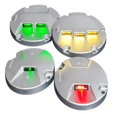
(2) Bidirectional LED Display Module: Supports multi-color display including red, yellow, green, and white. LED elements are arranged bidirectionally and support independent dynamic control by lane or group, enabling flashing, steady-on, or off states.
(3) Environmental Sensing Array: Integrates traffic flow, photosensitive, temperature, and vibration sensors to enable distributed collection of holistic road surface status and self-diagnostic state checking.
(4) Power Supply System: Supports both active power supply (DC 12V/24V/36V) and off-grid micro solar photovoltaic energy storage (continuous operating time of no less than 24×7 hours) in a cooperative supply configuration.
4.1.2 Advanced “Simultaneous Information and Energy Transmission” Wireless Technology Architecture
To address the structural damage to road surfaces caused by large-scale trenching and cable laying, advanced technology introduces a simultaneous information and energy transmission smart road marker architecture. Its LED indicators and sensor arrays are uniformly managed by an internal signal processing and transceiver module, maintaining real-time data exchange with the roadside RSU via high-speed wireless antennas. At the same time, the system incorporates an RF energy harvesting antenna and RF rectification module capable of wirelessly capturing and converting RF energy broadcast by RSUs or the surrounding environment into direct current, providing continuous power compensation for the data transceiver module.
4.1.3 LoRa-Based Wide-Area Low-Power Mesh Control
In scenarios such as long tunnels, sharp curves, or large-scale lane-level dynamic management, intelligent control solutions based on LoRa (Long Range Low Power wireless technology) offer significant advantages. LoRa networks achieve transmission distances of several kilometers with extremely low power consumption. Through LoRa data transmission units, roadside gateways or signal controllers can implement flexible free-grouping and convoy control of road markers, serving as a perfect complement to C-V2X/4G/5G high-bandwidth solutions.
4.1.4 Limitations of Traditional Luminous Road Markers
Compared to the networked markers with integrated multi-modal communication and high pressure resistance described above, early luminous road markers exhibit notable limitations: first, their communication range is typically ≤ 100 m with weak anti-interference capability, making reliable large-scale cluster networking on highway segments unfeasible; second, their mechanical strength is insufficient, making them highly susceptible to physical fracture and failure under prolonged, high-intensity repeated vehicle overrun.
4.2 Core Carrier of Digital Traffic Signs: Active Luminous Panel Display Signs
The physical manifestation of digital traffic signs relies primarily on active luminous panel display signs with internally configured LED light sources. Light is directed from behind the panel and projected through special translucent materials, producing extremely high color contrast.
4.2.1 Technical Classification
(1) Full-Face Backlit Traffic Signs: All graphics, text, symbols, and background colors possess active translucent luminous capability, with highly uniform luminance across the entire sign face.

(2) Partial-Face Backlit Traffic Signs: Only key information elements such as text strokes, core graphic symbols, and outer borders are backlit and transmissive, while the background remains non-luminous, resulting in lower energy consumption.
4.2.2 Core Materials and Process Performance
(1) Structure: Version 2.0 three-dimensional modular luminous unit design, with individual characters or single lines of text and graphics as embedded luminous bodies. Multiple distinct modules are assembled without ambiguity to compose information content. Information units and integrated circuits form a one-piece modular design, with each module performing a specific function and modules interacting through standardized interfaces, while achieving extremely light self-weight and strong wind load resistance.
(2) Frame, connections, and fasteners are all die-formed. A single drawing drives the entire output, standardizing engraving, lettering, and welding processes — with 50% automated processing of semi-finished components and 80% automated assembly for finished product output.
5. Discussion of Key Issues: Dynamic-Static Information Conflicts and Decoupling Pathways
In the practical deployment of intelligent connected control and vehicle-road collaborative systems, the most fundamental contradiction facing digital markings and signs is: when variable lane signs or smart road markers alter lane functions or traffic rules due to dynamic management, how should conflicts between these and the existing physical static markings on the road surface (such as traditional permanent thermoplastic markings) and static signs be handled?


5.1 This Contradiction Is Interwoven Across Three Deep Dimensions:
5.1.1 Legal and Liability Determination: Current traffic safety laws and regulations predominantly treat physical thermoplastic markings or static metal-plate signs as the sole legally recognized basis for enforcement. Digital dynamic signs and markings lack clearly defined legal priority authorization. Once a vehicle scrape or collision occurs due to a dynamic-static conflict, establishing accident liability becomes extremely difficult.
5.1.2 Human Behavioral and Cognitive Confusion: For conventional human drivers, if a smart road marker on the horizontal driving plane indicates a left turn (in a dynamically switched state) under dusk or adverse weather conditions, while the original white thermoplastic straight-ahead marking remains clearly visible on the road surface, the driver is confronted with contradictory visual streams. This cognitive dissonance produces severe decision hesitation, reaction times are multiplied, and rear-end collisions are easily triggered.
5.1.3 Multi-Source Perception Conflicts in Autonomous Driving: When the visual perception system of a connected and autonomous vehicle (CAV) encounters inconsistencies between physical paint-based forms and digital active-luminous forms, it triggers a fundamental confidence conflict within the onboard computer. In severe cases, this causes the system to frequently “downgrade” or execute erroneous actions such as emergency braking.
5.2 Systemic Decoupling and Resolution Pathways
To overcome this industry bottleneck, decoupling solutions must be advanced collaboratively across three dimensions — engineering, technology, and regulation:
5.2.1 Development of “Programmable Directional Optical Masking and Suppression Technology”: Increase the active luminous energy density and directional optical angular distribution of road surface smart markers and vertical signs. When activated, the high-brightness optoelectronic energy visually suppresses and overlays the underlying static physical paint or retroreflective film, allowing human eyes and onboard cameras to capture only the dynamic digital signal from specific viewing angles, fading out the static background.
5.2.2 Cloud-Road-Vehicle Multi-Source Data Fusion and Confidence Correction: Leveraging the “cloud + roadside + onboard” collaborative architecture. When lane functions switch, the roadside RSU not only changes the physical display but simultaneously converts the updated lane function (spatial variable) and signal timing data into structured V2X messages. At the algorithmic level, the onboard decision-making system elevates the confidence weight of V2X digital signals to the highest priority, thereby completely eliminating the interference of physical markings on autonomous vehicles.
5.2.3 Digital Space Priority Decoupling (Digital Legislation): Pilot programs to be initiated first in intelligent connected vehicle demonstration zones. Through legislation, it is explicitly stipulated that: “Under specific time periods, at specific signalized intersections, or during emergency events, digital dynamic variable information — including digital signs, smart road markers, and signal-linked states — shall hold absolute highest legal priority superseding static physical infrastructure.” This resolves conflicts from both the legal and algorithmic source simultaneously.
6. Outlook: The Future Landscape of Digital Traffic Signs and Markings
6.1 Deepening of Global Standardization and Normative Development
The foremost prerequisite for digital signs and markings to advance toward large-scale commercial deployment is standards-first. Future efforts must prioritize standardization work across two dimensions: first, the unification of information encoding rules — a unified digital data dictionary for signs and markings targeting globally connected vehicles must be developed and seamlessly integrated into SAE J2735, ISO, or ETSI standard protocols; second, the quantitative specification of communication and physical indicators — explicitly defining millisecond-level latency control for signs and markings cluster control under multi-modal communication standards including 5G-NR V2X and LoRa.
6.2 Comprehensive Deployment of an All-Scenario Intelligent Application Map
Digital signs and markings break free from the passive nature of traditional physical infrastructure; their dynamic programmability and spatiotemporal collaborative sharing characteristics will unlock dividends across intelligent scenarios:
6.2.1 Dynamic Lane Management in Smart Highway Work Zones and Accident Areas: Signs and markings operate in synchronized linkage to implement lane-level taper guidance and strong safety isolation for both distant and near-end traffic in advance.
6.2.2 All-Weather Active Protection Under Extreme Adverse Weather: Addressing the patchy fog, heavy rainfall, and black ice that frequently occur on highways, the signs and markings system adaptively adjusts brightness and flash matrices to provide vehicles with beyond-visual-range “fog-penetrating guidance lines” and dynamic speed limit directions.
6.2.3 Urban Expressway Tidal Lanes and Fine-Grained Flow Scheduling: Relying on cloud control platform commands, the horizontal marking colors and vertical divergence signs of an entire lane can be switched with a single command within milliseconds, achieving extreme spatiotemporal compression and dynamic adaptive allocation of physical lane resources.
6.3 Deep Integration into the “Vehicle-Road-Cloud” Three-Layer Collaborative Architecture
Future digital traffic signs and markings will completely leave behind their isolated physical form and evolve into the furthest networked nodes of the smart transportation perception and control network:
6.3.1 Cloud Control Platform: Responsible for strategic computation of macro-level global traffic flow, big data governance, and cross-regional long-distance remote diversion strategy coordination.
6.3.2 Roadside Edge: Roadside computing units (SDCU) aggregate multi-source perception data from radar, video, and other sensors, perform rapid local risk assessment, and issue commands so that vertical active-luminous signs and horizontal smart road markers achieve perfectly synchronized spatiotemporal switching of display states.
6.3.3 Onboard Terminal: Human drivers receive immediate guidance through high-brightness, high-contrast visual illumination within their instinctive field of view; connected and autonomous vehicles (CAVs) directly ingest digitally encoded rules via OBU, integrating them into motion planning and decision-making control.
6.4 Transition from Assisted Driving Information Supplement to Full-Stack Autonomous Driving Support
As intelligent highway infrastructure grades steadily advance toward the higher-order I4/I5 levels, the structured, high-redundancy digitally encoded information transmitted by digital traffic signs and markings will progressively evolve from the current role of “supplementary visual information” to a core infrastructure-level input source for autonomous driving perception systems (Infrastructure as a Sensor). It forms deep heterogeneous redundant fusion with onboard high-definition maps (HD Map), LiDAR, and camera vision. This “digital certainty” originating from roadside infrastructure can fundamentally overcome the physical bottlenecks of onboard visual sensors under adverse weather, strong reflective glare, physical occlusion by large vehicles, or blind-spot viewing angles at sharp curves.
6.5 Green, Sustainable, and Zero-Energy Evolution Direction
Against the macro backdrop of the global “dual carbon” goals and sustainable development, long-term operational energy consumption of infrastructure is a critical consideration that must be confronted for large-scale promotion. The “green self-sufficiency” of digital traffic signs and markings is poised for a breakthrough. Through deep research and integration of field RF energy harvesting, long-life wide-temperature solid-state/sodium-ion battery technology, high-efficiency micro photovoltaic panels, and even road surface piezoelectric and vibration energy generation technology, it is anticipated that near-zero external energy consumption (Zero-Net-Energy) over the full life cycle of large-scale distributed road markers and sign components will be achievable. Furthermore, based on advanced low-power LED chip design and intelligent adaptive brightness adjustment mechanisms, the system can not only effectively avoid light pollution but also suppress overall system power consumption to an extremely low level.
Conclusion
Digital traffic signs and markings are the core support for traffic infrastructure’s leap from traditional “physical carrying media” to modern “digital network nodes,” and the critical link for the full-stack engineering realization of vehicle-road collaboration and high-order autonomous driving. At present, this field is in a critical engineering window — one of standard formulation, complex scenario rehearsal, and breakthrough of dynamic-static information conflicts. Through globally coordinated advancement across law and regulation, optoelectronic materials, wireless communications, and edge algorithms, digital signs and markings systems will inevitably evolve into the “neural endings” of the smart road network, charting a safer, more efficient, and greener mobility future for all humanity.