By Gan Liu, Xiaogang Wang, Changze LI, Hao Wang
SYSTEM OVERVIEW
The I-ROAD Three-Level Signal Guidance and Control System is a unified intelligent transport platform that integrates regional routing guidance, dynamic lane function management, and adaptive traffic signal control. Underpinned by V2I (Vehicle-to-Infrastructure) communication technology and real-time holographic traffic data from connected-vehicle networks, the system simultaneously optimises the spatial and temporal dimensions of intersection control — breaking through the fundamental limitations of conventional time-only signal optimisation.
1. Background & Problem Statement
1.1 The Limits of Conventional Signal Control
Conventional traffic signal control treats road network geometry, vehicle arrivals, and intersection channelisation as fixed inputs, optimising only time variables — cycle length, green split, and phase offset. This produces a structural bottleneck: the system cannot respond to network-level routing effects, cannot influence vehicle arrival patterns, and cannot reconfigure lane functions. As a result, signal timing optimisation yields only marginal gains, and the system fails under saturated flow, demand surges, or non-standard traffic events.
Vehicle arrivals, road space allocation, channelisation, and signal timing are tightly coupled in practice — each is simultaneously an input to and an output of the others. Treating only one dimension as variable makes meaningful optimisation impossible.
1.2 The Connected-Vehicle Opportunity
The rise of intelligent connected vehicle (ICV) technology changes the fundamental data environment for traffic control. V2I communication enables roadside infrastructure — signs, signals, barriers, luminaires — to exchange high-precision, low-latency data with passing vehicles and with cloud management platforms in real time. This creates the technical precondition for a new generation of integrated, multi-dimensional traffic control.
China’s strategic target under ‘Made in China 2025’: reduce road traffic accidents by 80%, fatalities by 90%, and improve highway efficiency by 80% — driven in large part by intelligent connected vehicle infrastructure.
2. System Architecture
2.1 The Three-Level Structure

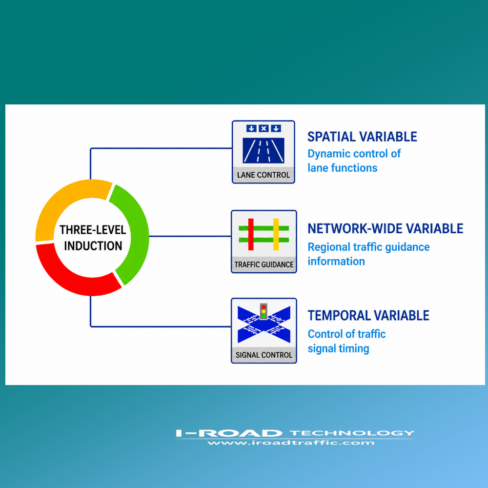
The system is built on a three-level control hierarchy, corresponding to the sequence in which vehicles encounter control devices as they approach an intersection. Each level addresses a distinct dimension of traffic control and communicates bidirectionally with vehicles via V2I.
Level 1 — Link Condition Guidance Sign
The first level device is a dynamic guide sign installed upstream of the intersection. It receives real-time data from vehicles on all connected downstream links, processes this data, and displays link-level traffic conditions — colour-coded as green (free flow), yellow (busy), or red (congested) — for each of the three possible onward directions (straight, left turn, right turn). Destination names and current link name are displayed alongside the directional arrows.

This level provides proactive route choice information, enabling drivers to divert before reaching the intersection — reducing concentrated demand and rebalancing pressure across the network.
Level 2 — Variable Lane Function Sign
The second level device is a variable lane function sign installed 50–100 m upstream of the stop line. It dynamically reassigns lane functions — for example, converting a straight-ahead lane to a left-turn lane during peak left-turn demand — in response to real-time flow imbalances between movements.
Conditions for variable lane deployment at a signalised approach include:

- Minimum three lanes on the approach (considering left turn and straight-ahead movements only)
- Minimum 120 m of upstream link length to accommodate sign installation
- Demonstrable time-of-day variation in the left-turn to straight-ahead flow ratio — i.e., tidal directional flow
Level 3 — Adaptive Signal Control
The third level is the traffic signal controller, which must be synchronised with variable lane function changes. Signal control in this system comprises two components: phase plan selection and signal timing optimisation.
Four phase plan types are supported and selected based on approach geometry and flow conditions:
- Symmetric (dual-ring) release — efficient for balanced opposing flows; typically four phases covering straight-ahead and left-turn movements from each approach
- Single-approach release — all movements from one approach per phase; high safety, complete conflict separation
- Mixed release — combines symmetric and single-approach elements; effective for tidal flow conditions
- Overlap (leading/lagging) release — applied when flow imbalances exist between opposing approach pairs; uses leading and lagging left-turn phases to accommodate asymmetric demand

Signal timing is optimised using the Webster model, minimising total intersection delay. Green split is allocated proportionally to movement volume-to-saturation-flow ratios, and is recalculated whenever lane function is reassigned.

3. Communication Architecture
3.1 V2I Network Design
node. The RSU maintains real-time bidirectional data exchange with all field devices and with the cloud management platform via advanced wireless communications and next-generation internet protocols. DSRC (Dedicated Short-Range Communications) provides high-speed I2V links to On-Board Units (OBU) in passing vehicles.
Key RSU communication interfaces:
- RSU ↔ Signal Controller: protocol-based or universal I/O interface for real-time monitoring and phase control
- RSU ↔ Variable Lane Signs: real-time status acquisition and cloud-commanded function switching
- RSU ↔ Link Condition Guide Signs: operational monitoring; real-time travel time and network condition updates
- RSU ↔ Local Detectors: periodic full-sample data exchange
- RSU ↔ Internet: network-wide travel time and link condition data from mapping platforms
- Cloud Platform ↔ Active Luminous Signs: ambient light and weather-triggered illumination control
- RSU ↔ OBU (vehicles): DSRC high-speed connection for I2V information delivery
3.2 Field Device Deployment Positions
Device deployment follows a defined spatial sequence relative to the stop line:
| Device | Position | Function |
| Link Condition Guide Sign | Upstream of approach | Route choice guidance; network pressure rebalancing |
| Variable Lane Sign | 50–100 m upstream of stop line | Dynamic lane function assignment; flow equalisation across movements |
| Signal Controller | At stop line | Phase, sequence, green split, offset — synchronised with lane function changes |
System device deployment layout showing spatial relationships between the three control levels.
4. Simulation Validation
4.1 Simulation Setup
To validate system effectiveness, a microsimulation experiment was designed around an isolated signalised intersection. The target approach had four lanes: dedicated left turn, shared left-turn/straight-ahead (the variable lane), dedicated straight-ahead, and dedicated right turn. The variable lane was initialised as straight-ahead. Left-turn demand was progressively increased relative to straight-ahead demand during the simulation to trigger variable lane switching.
4.2 Results: Level 1 — Link Condition Guidance4.2 Results: Level 1 — Link Condition Guidance

As left-turn demand increased, the link condition guidance sign detected deteriorating conditions on two downstream links. The status indicators for those links changed from green (free flow) to yellow (busy), correctly reflecting the emerging congestion. The system demonstrated accurate, real-time link condition detection and display.
4.3 Results: Level 2 — Variable Lane Switching
When the system detected that the left-turn queue length exceeded the configured switching threshold, it reassigned the variable lane from straight-ahead to left-turn function and simultaneously recalculated signal timing based on the new lane configuration.

4.4 Results: Queue Length and Delay
Simulation results demonstrated clear performance improvements after variable lane activation:
| Metric | Outcome | Observation |
| Left-turn queue | ↓ Significantly | Queue reduced to clearable within green time after switching; previously uncleared under fixed lane configuration |
| Left-turn delay | ↓ Significantly | Reduction observed from 4th signal cycle onward — the cycle in which switching threshold was first reached |
| Straight-ahead queue | ↑ Marginally | Minor increase due to lane loss; total increase substantially smaller than left-turn queue reduction |
| Straight-ahead delay | ≈ Unchanged | No statistically significant increase in straight-ahead delay — confirming net benefit of lane reassignment |
The net result: the reduction in left-turn queue length and delay substantially exceeded the marginal increase in straight-ahead delay, confirming that variable lane switching produces a clear net improvement in approach-level performance.


5. System Advantages
The following capabilities define the Three-Level System’s differentiation from conventional signal control approaches:
| Space-Time Cooperative OptimisationLane function (spatial variable) is incorporated as a direct input to signal timing computation. Temporal and spatial control variables are jointly optimised in a single framework — breaking through the optimisation ceiling of time-only signal plans and delivering exceptional adaptability across a wide range of demand patterns. |
| Network-Level and Node-Level Joint ConsiderationAt the node level, movements and individual lanes are the basic control units. At the network level, the system monitors saturation and queue length on critical paths, achieving network-wide traffic pressure equalisation alongside intersection-level optimisation. |
| Proactive and Reactive Traffic ManagementMacro-level: the system predicts area-wide conditions and publishes routing guidance through active luminous signs, actively steering driver route choices before the intersection. Micro-level: the system implements tactical signal and lane adjustments in response to real-time arriving flows. |
| Big Data and High-Resolution Local Data CombinedInternet-sourced data (navigation platforms) provides network travel time estimation and link condition monitoring for area-wide signal plan adjustment. Full-sample, high-resolution local detector data provides the precision inputs for intersection-level optimisation. Both data streams are integrated into a single computation environment. |
| Cloud-Edge Cooperative ArchitectureA high-performance RSU at each intersection serves as the edge convergence node, communicating simultaneously with the signal controller, variable lane signs, and guide signs. Cloud and edge management functions are distributed for resilience and low-latency response. |
| Active Luminous and Intelligent IlluminationActive luminous signs extend recognition distance, maintain legibility in adverse weather conditions, and increase driver decision time — directly improving road safety. Sign illumination is controlled by time-of-day schedule or dynamically by ambient light sensors and meteorological data. |
| Digital and Networked InfrastructureGuide signs incorporate embedded NB-IoT modules, enabling connection to the smart IoT transport infrastructure cloud platform. Sign identity information is fully digitised, providing the V2X technical foundation for vehicle-road cooperation at scale. |
6. Deployment & Track Record
The Three-Level Signal Guidance and Control System has been demonstrated in China’s first connected vehicle pilot zone. Field deployment confirmed that the approach is technically effective, operationally reliable, and economically viable. The system successfully handled the full range of operational scenarios:
- Routine daily demand fluctuations and peak-hour management
- Traffic incident detection and response
- Major event traffic management
- Law enforcement and special operations
- Adverse weather conditions
Field results confirmed: the system delivers measurable, sustained relief from urban traffic congestion — not as a theoretical model, but as a deployed, operational infrastructure solution.
7. Intellectual Property & Standards
The technologies embodied in this system are protected by invention patents held by I-ROAD Technology Co., Ltd. in China. This documentation represents the first public international release of the system overview. All technology is independently developed by I-ROAD and is capable of accommodating client-specific functional customisation.
Certification of field devices follows applicable national or regional technical standards in the jurisdiction of deployment. Technical parameters for individual system components are documented in the corresponding product specification sheets available on this website.
This system description draws on peer-reviewed research published by Southeast University (School of Transportation) and Jiangsu Technology Innovation & C-V2X Academy, confirming independent academic validation of the system’s technical approach and simulation results.
(Note: This paper was originally published in China Traffic Science & Technology in 2020 and is reproduced here in English for international dissemination.)